Copper-Aluminum Transition Connectors for Photovoltaic Systems: A Practical Engineering Guide
- Share
- publisher
- SUNKEAN
- Issue Time
- Jul 16,2026
Summary
Exploring copper-aluminum transition connectors in photovoltaic systems: galvanic corrosion challenges, bimetallic lug design, installation best practices, and how proper material selection ensures 25-year solar plant reliability.
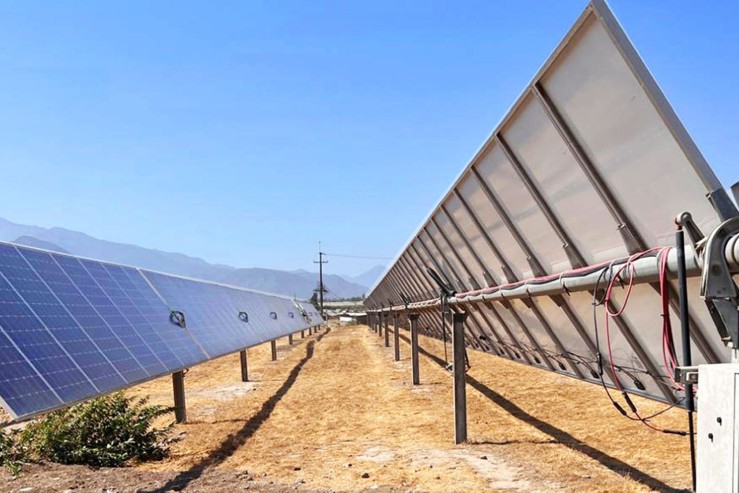
Solar farms don't fail because panels degrade. They fail because connections corrode. After auditing dozens of utility-scale PV plants across Southeast Asia and the Middle East, one pattern shows up again and again: the junction where copper meets aluminum is where trouble begins. This isn't a materials defect. It's a electrochemistry problem. When copper and aluminum sit in direct contact and moisture enters the picture, galvanic corrosion eats away at the aluminum side within months, not years. The connection resistance climbs, heat builds up, and eventually you get a thermal event or a string dropout that nobody catches until the monitoring dashboard shows a 15% yield drop. The fix isn't complicated. But it has to be engineered correctly from the start. This guide walks through copper-aluminum transition technology for PV systems — what works, what doesn't, and how to specify connections that last the full 25-year module warranty. Here's the reality of modern solar projects: aluminum cables dominate the DC side because they're cheaper, lighter, and easier to pull through long conduit runs. But the internal wiring of PV modules, junction boxes, and inverters almost always uses copper busbars and terminals. Somewhere between the string and the inverter, these two metals have to meet. You could use all-copper cabling, and some premium installations do. But for a 50 MW solar farm where you're pulling cables across hundreds of meters, the cost difference between copper and aluminum conductors can run into six figures. Aluminum wins on economics. Copper wins on reliability at termination points. The engineering challenge is making the transition safely. The galvanic corrosion problem: Copper sits at +0.34V on the standard electrode potential scale. Aluminum sits at -1.66V. That's a 2.0V difference. When an electrolyte (even humidity) bridges the junction, the aluminum becomes the sacrificial anode and dissolves. This isn't theoretical — it's measurable in the field within 6 to 18 months of exposure. The industry-standard solution is the bimetallic transition lug. These connectors weld a copper pad to an aluminum barrel using friction welding, creating a molecular bond that eliminates direct copper-to-aluminum contact at the termination surface. Here's how a typical bimetallic lug is constructed: The key insight: the welded interface means current flows from aluminum to copper through a solid-state bond, not through a mechanical contact point. There's no air gap, no exposed dissimilar-metal junction, and no path for galvanic corrosion. Not all copper-aluminum connectors are created equal. When specifying connectors for a solar project, these are the parameters that actually matter: The connector must handle the continuous DC current of the string at the site's maximum ambient temperature. A common mistake is sizing the connector to the cable's ampacity without accounting for the temperature derating curve. At 70°C ambient (typical for rooftop solar in tropical climates), a 150A-rated lug might only be safe at 110A. The joint compound matters more than people think. Look for connectors pre-filled with zinc-oxide or copper-oxide-based oxide inhibitors that meet ASTM B812. Cheap petroleum-jelly substitutes dry out within two years and leave the joint unprotected. After crimping, the connection should withstand a pull force of at least 40% of the conductor's rated breaking strength per IEC 61238-1. If a tug test fails, the crimp die or the lug barrel is wrong for that conductor. For outdoor PV combiner boxes, the connector must maintain IP65 or better when properly assembled. Heat-shrink tubing with adhesive lining should cover the crimped barrel to prevent water tracking along the conductor insulation. Even the best connector fails if installed poorly. These field practices separate 25-year installations from 5-year ones: Aluminum forms a hard oxide layer within seconds of exposure to air. Before inserting the conductor into the lug barrel, scrub the exposed section with a stainless steel brush and immediately coat it with oxide inhibitor. Skip this step, and you're crimping onto an insulating layer. Every manufacturer publishes a crimp die chart. Using a "close enough" die leaves voids in the crimp, which become hot spots under load. Hexagonal dies are standard for most PV lug designs, but some require point-to-point or indentation crimping. There's no universal die. For the copper palm side, use a calibrated torque wrench set to the manufacturer's specification. Over-torquing cold-flows the copper and reduces contact pressure over time. Under-torquing leaves the joint loose from day one. Most PV bimetallic lugs specify 8-12 Nm for M8 hardware, but always check the datasheet. Aluminum expands about 42% more than copper for the same temperature rise. After the first 50 thermal cycles (roughly two months of operation), re-check torque on every bolted joint. This single maintenance step catches 80% of would-be thermal failures. The combiner box is where multiple string cables converge onto a common copper busbar. It's also where power distribution and copper-aluminum transitions are most concentrated — and most likely to be installed by different crews on different schedules. Field finding: In a 2023 audit of 12 utility-scale solar plants in the Philippines, 7 had at least one combiner box with signs of thermal degradation at copper-aluminum junctions. The common thread: no oxide inhibitor applied during installation, and no re-torque after commissioning. Best practice for combiner box wiring: When sourcing copper-aluminum transition connectors for PV projects, these are the certifications that carry weight: No. A standard copper lug crimped onto an aluminum conductor creates a direct dissimilar-metal contact point. Without the friction-welded bimetallic interface, galvanic corrosion will degrade the joint within months. Always use a purpose-built bimetallic transition connector. When installed with oxide inhibitor, correct crimping, and proper sealing, bimetallic transition connectors are rated for 25-30 years of service. They should match or exceed the PV module warranty period. The key variable is maintenance — re-torquing after the first thermal cycling period extends service life significantly. In most jurisdictions, yes. NEC 110.14 in the United States requires that connectors be listed for the materials being joined. IEC standards similarly require that dissimilar metal connections use approved transition methods. Using non-listed connectors can void insurance coverage and project certifications. Typically 2 to 4 times the cost of a standard copper lug of equivalent current rating. However, on a project basis, the connector cost is negligible compared to the cable cost. A 1% increase in total connection cost prevents what could be a six-figure repair bill from a thermal failure event. Copper-aluminum transition connectors aren't glamorous. They don't show up in renderings or marketing brochures. But they're the single most common failure point in utility-scale PV plants, and they're also one of the cheapest things to get right. The formula is straightforward: specify IEC 61238-1 or UL 486B listed bimetallic lugs, apply oxide inhibitor properly, crimp with the correct die, torque to spec, and re-check after the first thermal cycling period. Do these five things, and your PV connection points will outlast the modules themselves. For projects looking at 25-year performance guarantees, the connector specification deserves the same engineering rigor as the module selection. Cut corners here, and the savings on lug cost will vanish in the first year of O&M expenses.
Why Copper and Aluminum Must Coexist in Solar Installations
Bimetallic Transition Connectors: How They Work

Specification Checklist for PV Transition Connectors
1. Current Rating and Temperature Rise
2. Oxide Inhibitor Quality
3. Mechanical Pull Strength
4. Environmental Sealing
Installation Practices That Prevent Failures
Brushing the Aluminum Conductor
Using the Correct Crimp Die
Torque, Not "Tight Enough"
Re-Torquing After Thermal Cycles
The PV Combiner Box: Where Most Problems Hide

Standards and Certifications to Look For
Standard What It Covers Why It Matters for PV IEC 61238-1 Compression and mechanical connectors for power cables Defines pull-out force and resistance stability after thermal cycling UL 486B Wire connectors for aluminum conductors Required for NEC-compliant installations in North America ASTM B812 Oxide inhibitor compound specifications Ensures the joint compound won't dry out or become conductive IEC 62817 Design qualification for solar PV junction boxes Covers environmental sealing and long-term reliability Frequently Asked Questions
Can I connect copper and aluminum cables directly with a regular lug?
How long do properly installed bimetallic connectors last?
Are bimetallic connectors required by code?
What's the cost premium of bimetallic lugs over standard copper lugs?
Bottom Line