Current Collection and Trunk Harness Solutions: Engineering Reliable Power Distribution Networks
- Share
- publisher
- SUNKEAN
- Issue Time
- Jul 14,2026
Summary
From metro transit current collection systems to industrial trunk cable harnesses, examining design principles, material selection, vibration resistance, and how modern harness engineering balances current density with long-term durability.
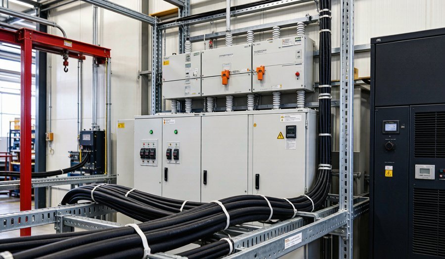
Every electric subway car draws 1500A from a third rail. Every arc furnace in a steel mill pulls 50,000A through a busbar trunking system. Every wind turbine nacelle routes 3000A from the generator to the base through a 90-meter cable harness. These are the unsung systems that make modern infrastructure work — and when they fail, the consequences are measured in millions of dollars per hour of downtime.
Current collection and trunk harness engineering sits at the intersection of power electronics, materials science, and mechanical design. It's not glamorous work, but it's the kind of engineering that determines whether a metro system runs for 40 years or needs a full overhaul after 15.
This guide covers the design principles, material selection, and application scenarios for current collection systems and trunk cable harnesses across transit, industrial, and renewable energy applications.
What Is a Current Collection System?
A current collection system is the physical interface between a moving electrical load and a stationary power source. The most visible examples are pantographs on electric trains and third-rail shoes on subway cars, but the category also includes collector shoes for overhead cranes, sliding contacts for automated guided vehicles (AGVs), and brush assemblies for industrial rotary equipment.
The engineering challenges are unique because current collection involves a sliding electrical contact that must maintain low resistance while withstanding mechanical wear, vibration, and environmental exposure. Unlike bolted or crimped connections, sliding contacts lose material over time and must be serviced or replaced on a predictable schedule.
Design reality: A metro system running 30 trains per hour through a single substation can wear through 2-3mm of collector shoe material per week. The current collection system must deliver 1500A at 750V DC with a contact resistance under 0.5 milliohms — while the contact surface is actively eroding.
Key Components of Trunk Cable Harness Systems
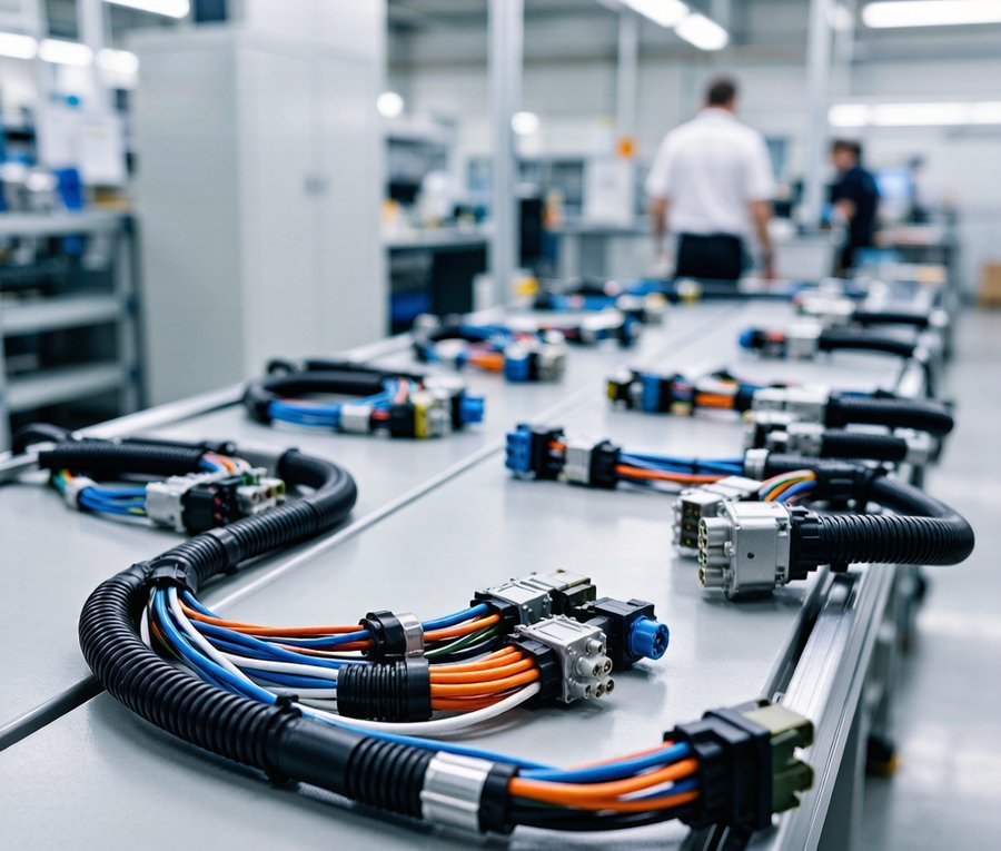
Trunk cable harnesses differ from standard building wiring in one critical way: they're engineered as complete systems, not collections of individual cables. A trunk harness bundles multiple conductors, shielding layers, support structures, and termination hardware into a single assembly that's tested and qualified as a unit.
Conductor Configuration
Trunk harnesses typically use parallel conductor arrangements rather than twisted pairs. For DC power distribution, the positive and negative conductors run side by side to minimize the loop area and reduce inductance. For AC three-phase systems, the three phases and neutral are arranged symmetrically to balance electromagnetic fields and reduce eddy current losses in adjacent metallic structures.
Shielding and Grounding
In high-current trunk harnesses, electromagnetic interference (EMI) is a first-order concern. A 1000A AC cable generates a magnetic field strong enough to induce circulating currents in nearby steel structures, causing heating and energy losses. Shielding approaches include:
- Aluminum foil wrap: Lightweight, effective for high-frequency EMI. Common in transit applications.
- Copper braid shield: Higher conductivity, better for low-frequency magnetic field shielding. Used in industrial harnesses.
- Steel armor: Provides mechanical protection and magnetic shielding. Standard for underground trunk cables.
- Segregated phase arrangement: Physically separating each phase into its own steel conduit eliminates magnetic coupling between phases. Common in high-current switchgear connections.
Thermal Management
A trunk harness carrying 2000A dissipates significant heat. The conductor temperature rise depends on the cross-section, insulation thermal conductivity, and ambient conditions. For a typical 400mm² copper conductor in free air, 2000A produces a steady-state temperature rise of about 35°C above ambient. In a bundled harness with multiple conductors, the mutual heating effect can push the inner conductors 15-20°C hotter than the outer ones.
Thermal design strategies include:
- Using larger conductor cross-sections than the ampacity table requires, to reduce operating temperature
- Specifying insulation materials rated for continuous operation at 105°C or higher (silicone, mica-glass)
- Including thermal break layers between adjacent conductors to reduce mutual heating
- Designing the harness routing to avoid heat traps near engine compartments or furnace enclosures
Vibration and Mechanical Resilience
Trunk harnesses in transit and industrial applications face continuous vibration that would destroy standard building wiring within months. A subway car's undercarriage harness experiences 5-50 Hz vibration at 2-5g acceleration for 18 hours per day. The harness design must account for:
- Strain relief at every termination: Cable lugs must have mechanical support that prevents flexing at the crimp joint. A unsupported cable vibrating at 5g will work-harden and fracture at the lug within 100,000 cycles.
- Flexible conductor class: Class 5 or Class 6 flexible stranded conductors (per IEC 60228) survive vibration far better than rigid solid conductors. The trade-off is slightly higher resistance due to reduced packing density.
- Vibration-damped mounting: Rubber isolation mounts at 300-500mm intervals absorb vibration before it reaches the conductor. Hard-mounted clips transmit vibration directly to the copper.
- Service loop design: Every harness should include a service loop — extra length that allows for thermal expansion, vibration movement, and future re-termination without replacing the entire harness.
Busbar Trunking Systems: An Alternative to Cables
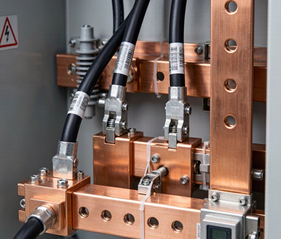
For very high current applications (2000A+), busbar trunking systems often outperform cable harnesses. A busbar trunk is a prefabricated assembly of flat copper or aluminum bars housed in a protective enclosure, with tap-off points at regular intervals for load connections.
| Factor | Busbar Trunking | Cable Harness |
|---|---|---|
| Current capacity | Up to 6300A | Up to 2000A per conductor |
| Voltage drop | Lower (shorter path, larger cross-section) | Higher (longer path, circular cross-section) |
| Flexibility | Rigid, fixed routing | Flexible, can follow any path |
| Installation speed | Fast (modular sections bolt together) | Slower (individual cable pulling and termination) |
| Tap-off points | Built-in, plug-in modules | Requires junction boxes |
| Cost (materials) | Higher per meter | Lower per meter |
| Cost (installation) | Lower | Higher (labor-intensive) |
In practice, most industrial power distribution systems use a combination: busbar trunking for the main distribution spine (where current is highest and routing is straight), and cable harnesses for branch circuits (where flexibility and routing around obstacles matter more than raw current capacity).
Application Scenarios
Transit Current Collection (Metro and Light Rail)
Third-rail current collection systems in metro networks use collector shoes made of carbon or copper-impregnated steel that slide along an energized rail. The shoe assembly includes a spring-loaded holder that maintains 80-150N of contact force against the rail. The trunk harness connects the shoe assembly to the train's DC bus, typically using 150-300mm² flexible copper cables rated for 1500V DC.
Design priorities: wear resistance (shoes are consumable), vibration resilience (the shoe bounces on the rail at every joint gap), and fault current handling (short circuits at the rail can deliver 30,000A+ for several cycles before the substation breaker trips).
Industrial Power Distribution (Steel, Mining, Chemical)
Heavy industry uses trunk harness systems to route power from main switchgear to production equipment. A typical steel mill might have a 15-meter busbar trunking run from the 33kV/690V transformer to the main distribution panel, then cable harnesses branching to individual arc furnaces, rolling mill motors, and auxiliary equipment.
Design priorities: thermal endurance (ambient temperatures near furnaces can reach 70°C), chemical resistance (sulfur, chlorine, and oil exposure degrade standard insulation), and fault tolerance (a single harness failure shouldn't shut down the entire production line).
Renewable Energy (Wind and Solar)
Wind turbine nacelles contain trunk harnesses that route power from the generator down the tower to the base-mounted transformer. A 5 MW turbine might use a 6-parallel cable harness rated for 3000A at 690V AC, running 90 meters vertically through the tower.
Design priorities: weight (every kilogram in the nacelle adds to structural loads), torsional flexibility (the nacelle rotates to face the wind, twisting the harness), and lightning protection (the harness must include grounding conductors that can carry 200kA lightning surge currents without fusing).
Material Selection Guide
The choice of conductor and insulation materials drives both the performance and the cost of a trunk harness system:
| Component | Options | Best For |
|---|---|---|
| Conductor | Copper (high conductivity), Aluminum (lightweight), Copper-clad aluminum (compromise) | Copper for max current density; aluminum for long runs where weight matters |
| Insulation | XLPE (90°C), Silicone (200°C), ETFE (150°C), mica-glass (600°C) | XLPE for general industrial; silicone for transit; mica-glass for furnace areas |
| Shield | Aluminum foil, copper braid, steel armor | Foil for EMI; braid for magnetic fields; armor for mechanical protection |
| Connector | Crimp lugs, bolted joints, compression connectors | Crimp for permanent joints; bolted for serviceable connections |
| Jacket | PVC, PUR, CPE, halogen-free | PVC for indoor; PUR for abrasion resistance; halogen-free for transit |
Frequently Asked Questions
What's the difference between a cable harness and a cable assembly?
A cable assembly is a single cable with connectors on both ends. A cable harness is a bundle of multiple cables routed together, tied or sleeved as a unit, and terminated at multiple points. Harnesses are used when multiple signals or power circuits need to follow the same physical path. Assemblies are used for point-to-point connections.
How do I calculate the current rating of a bundled trunk harness?
Bundled cables derate more than single cables because of mutual heating. The standard approach is to calculate the single-cable ampacity per IEC 60364-5-52, then apply a grouping derating factor. For 6 cables touching in a single layer, the derating factor is typically 0.72. For 6 cables in a triangular bundle, it's 0.60. Always verify with the specific installation conditions — ambient temperature, thermal insulation, and ventilation all affect the final rating.
When should I use busbar trunking instead of cables?
Busbar trunking is preferred when the continuous current exceeds 2000A, when the routing is straight and horizontal, when tap-off points are needed at regular intervals, and when installation speed is critical. Cable harnesses are preferred when the routing is complex, when vibration or flexing is expected, and when the current is below 2000A per circuit.
What maintenance do trunk harness systems need?
Visual inspection every 6 months for insulation damage, thermal imaging annually for hot spots at connection points, torque verification on bolted joints every 2 years, and replacement of collector shoes (for transit systems) based on wear measurement schedules. For industrial harnesses in harsh environments, dielectric strength testing every 3-5 years is recommended.
Engineering Reliable Power Distribution
Current collection and trunk harness systems are foundational infrastructure — literally the arteries through which electrical power flows to keep cities moving, factories running, and renewable energy reaching the grid. The engineering decisions made during the design phase ripple through decades of operation.
The principles are consistent across applications: specify conductors with adequate cross-section for thermal performance, not just ampacity; choose insulation materials rated for the actual operating environment, not just the nominal temperature; design mechanical support for the vibration profile the harness will actually experience; and build maintenance access into the physical layout from the start.
Get these fundamentals right, and the system will deliver decades of reliable service. Get them wrong, and the failures will be expensive, disruptive, and entirely predictable.