Energy Storage System Connection Solutions: Cable Selection, Safety Standards, and Engineering Best Practices
- Share
- publisher
- SUNKEAN
- Issue Time
- Jul 14,2026
Summary
A field-oriented look at energy storage connection engineering: from cell-level busbar design to container-level power cabling, covering UL 1973, IEC 62619 compliance, thermal management, and connector selection for grid-scale BESS.
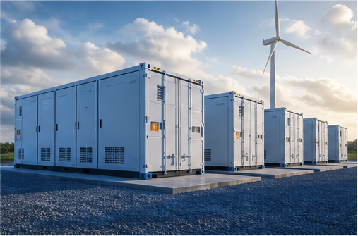
A 20-foot container holds roughly 3.7 MWh of energy. That's enough to power 350 homes for an hour. Every one of those watt-hours passes through cable connections, busbar joints, and connector hardware that must handle currents upward of 1500A DC — sometimes continuously, sometimes in 200-millisecond bursts when the grid frequency drops. Energy storage system (ESS) connections operate in a regime that no other power system quite matches: high current, frequent cycling, thermal swings from -20°C to 55°C, and zero tolerance for failure because a single bad joint can trigger thermal runaway. The engineering behind these connections is specialized, and the standards are still catching up to the deployment scale. This article breaks down the connection architecture of grid-scale battery energy storage systems (BESS), from cell-level interconnects to container-level power cabling, and covers the design choices that separate reliable systems from liability. Every grid-scale energy storage system has three distinct connection tiers, each with different current ratings, mechanical requirements, and failure modes: Inside each battery module, individual cells connect via aluminum or copper foil laser-welded to the cell terminals. These interconnects carry 50-200A per cell and must maintain sub-milliohm contact resistance. The welding quality directly determines whether a module passes factory testing or develops an internal hot spot three years into operation. Modules bolt onto rack busbars that aggregate current from 10-20 modules in series. These busbars typically handle 200-500A continuously and up to 1000A during peak charge/discharge events. The connection points use bolted joints with Belleville washers to maintain contact pressure through thermal cycling. The rack busbars connect to the container's DC distribution panel via heavy-gauge power cables — typically 95mm² to 240mm² copper or aluminum. These cables carry the full string current to the power conversion system (PCS). This is where most field-installed connections live, and where most connector selection mistakes happen. Design rule: The DC-side connection architecture must be rated for the maximum short-circuit current of the battery rack, not just the nominal operating current. A 1500V DC system with a 250kWh rack can deliver fault currents exceeding 25,000A for several milliseconds before the fuse clears. Connectors rated only for continuous current won't survive that event. Selecting energy storage cables for battery storage DC connections involves parameters that standard building wiring doesn't worry about: The cable insulation material matters too. XLPE (cross-linked polyethylene) is the workhorse for fixed BESS installations. For connections that need to flex during maintenance — like the service loop between the rack and the container wall — flexible silicone or ETFE-insulated cables hold up better over repeated bending. BESS installations use four main energy storage connector families. Each has its place, and mixing them up causes problems: The default for permanent rack-to-cable joints. Copper or bimetallic lugs crimped onto the cable and bolted to the busbar. Simple, reliable, and field-serviceable. The downside: requires torque verification during commissioning and after thermal cycling. Best for connections that won't be disconnected regularly. Used where modules need to be swapped during maintenance. Rated for 200-600A with integrated touch-safe features. The advantage is speed — a technician can disconnect a module in under 30 seconds. The trade-off is higher cost and a more complex current path that can develop resistance if the contact wipe area gets contaminated. For module-to-rack connections inside the battery cabinet. Belleville spring washers maintain contact pressure through thermal expansion cycles without requiring re-torquing. Critical for connections that experience daily charge/discharge thermal cycling. Used in cell-level interconnects inside modules. Laser welding or ultrasonic welding creates a permanent, zero-resistance joint. Not field-serviceable, but eliminates the contact resistance variability that plagues mechanical joints at high currents. Every connection in a BESS generates heat. A 1500A connection with 0.1 milliohm contact resistance dissipates 225W — that's a small heater running continuously at the joint. In an enclosed rack with limited airflow, multiple hot connections can raise the local temperature by 10-15°C above ambient, which accelerates insulation aging and increases battery self-discharge rates. Thermal design considerations for connection points: Beyond the power connections, every BESS has a network of signal cables connecting the battery management system (BMS) to each module. These low-voltage connections carry voltage and temperature data that the BMS uses to balance cells and prevent overcharge conditions. BMS signal wiring doesn't carry high current, but it has its own set of failure modes: The regulatory landscape for energy storage connections is maturing rapidly. These are the standards that project developers and EPCs should be specifying: It depends on the rack current and the cable run length. For a typical 100kW rack at 1500V DC (roughly 67A continuous), a 35mm² copper cable is usually sufficient. For higher-current racks (200kW+), 95mm² or 120mm² cables are common. Always verify with a voltage drop calculation — DC resistance losses add up quickly over long cable runs inside the container. No. DC and AC have different arc extinction characteristics. A cable rated for 1000V AC may only be safe at 600V DC because DC arcs don't self-extinguish at zero-crossings. Use cables specifically rated for DC voltage with appropriate insulation testing per IEC 62838. For grid-scale systems, thermographic inspection of all connection points should happen quarterly. Bolted joints should be re-torqued annually. Quick-disconnect connectors should be cycled (disconnected and reconnected) every 6 months to clean the contact surfaces and prevent oxide buildup. For a properly installed bolted joint carrying 1000A+, contact resistance should measure under 50 microhms. Anything above 100 microhms at full current will generate excessive heat and should be disassembled, cleaned, and re-torqued. Use a micro-ohmmeter for accurate measurement — standard multimeters don't have the resolution. Energy storage connection engineering doesn't get the attention that cell chemistry or PCS efficiency receives. But from a system reliability standpoint, it's where the rubber meets the road. A BESS with the best lithium iron phosphate cells and a 99% efficient inverter will still underperform if a single rack connection develops high resistance and forces the BMS to derate the string. The path to reliable BESS connections is unglamorous but proven: specify DC-rated cables with proper flame retardancy, use the right connector family for each application, design for thermal management at every joint, and build a maintenance schedule that includes thermal imaging and torque verification. Do this, and your energy storage system will deliver its rated capacity for the full warranty period — and beyond. For broader power distribution network engineering across transit and industrial applications, the same principles of conductor sizing, thermal management, and connection reliability apply at even larger current scales.
The Three Connection Layers in a BESS
Layer 1: Cell-to-Cell Interconnects
Layer 2: Module-to-Rack Busbars
Layer 3: Rack-to-PCS Power Cables
Cable Selection for BESS DC Side
Parameter Typical BESS Requirement Why It Matters Voltage Rating 1500V DC or 2000V DC DC arc extinction is harder than AC; insulation must be rated for DC specifically Temperature Class -40°C to +90°C Battery containers experience wide thermal swings; cable insulation must not embrittle or soften Flame Retardancy IEC 60332-1 or UL VW-1 Prevents flame propagation along cable runs in the event of a cell thermal event Smoke Emission IEC 61034 low-smoke Reduces toxic gas release in enclosed container environments Flex Cycles 500+ cycles (for service loops) Maintenance access requires flexing cables without cracking insulation Connector Types and When to Use Each
Bolted Lug Connections
Quick-Disconnect Power Connectors
Busbar Joints with Spring Washers
Fusion-Spliced Joints

Thermal Management at Connection Points
BMS Wiring: The Nervous System
Safety Standards for BESS Connections
Standard Scope Relevance to Connections UL 1973 Batteries for stationary applications Includes connection integrity testing under thermal abuse IEC 62619 Secondary lithium cells for industrial use Requires connection system fault testing UL 9540 Complete energy storage system certification Tests connection points during fire propagation events NFPA 855 Fire code for BESS installations Specifies separation distances and thermal barriers at connection points IEC 62933 Energy storage system integration Covers electrical interface and connection design requirements Frequently Asked Questions
What cable size do I need for a 1500V DC BESS rack connection?
Can I use AC-rated cables for DC battery connections?
How often should BESS connections be inspected?
What's the maximum contact resistance for a BESS power connection?
Closing Thoughts